Power supply and current regulator EZP-51
Technical description 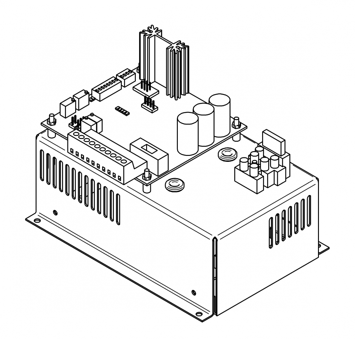
The controller is designed to electromagnetic particle control brakes and clutches in one of the 3 operating modes:
- control using 0-10 V differential voltage input signals
- control using 4-20mA differential current input signals
- control using a 10 kΩ potentiometer
The above mentioned modes permit brake and clutch control across the whole braking moment range of the respective brake or clutch type.
Cooperating equipment, which generate the control signal (e.g. inductive transducers, ultrasonic sensors and proximity sensors, etc.) can be supplied off the terminal strip, using the terminal no. 6, labelled Uin '+' 24VDC 100mA , and terminal 4 '-' labelled GND, while not to exceeding the maximum permissible current draw of 100 mA.
The residual magnetism reduction system utilized, permits operation across a broad parameters range and with high dynamics of braking moment variation. Braking moment is changed by proportionately altering the current flowing in the brake circuit, depending on the control signals. Current stabilization circuits used in the controller ensure constant value of the braking moment.
DESIGN AND AVAILABLE VERSIONS
The controller consists of three main components: a power supply module, a current source, which supplies brake coil and residual magnetism automatic control system for the electromagnet. The power supply module is housed inside a metal enclosure, whereas the remaining components are placed outside of the enclosure.
AVAILABLE CONTROLLER VERSIONS:
- EZP51-4 Controller card only
- EZP51-3 Controller card with 10 kΩ potentiometer
- EZP51-2/100-250 Controller card with 100-250V AC/30V DC power supply module
- EZP51-1/100-250 Controller card with 100-250V AC/30V DC power supply module and 10kΩ potentiometer
